|
O
|
 |
PROFI-TRACKER XL
What do the capacities of the new product look like?
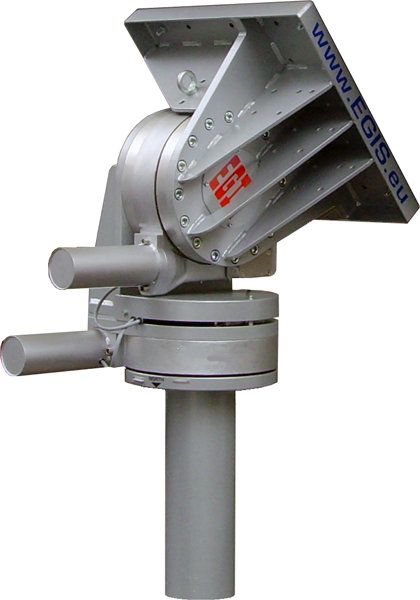
- Exceptionally easy and fast installation, and yet a highly accurate alignment due to the utilization of one motor each for the angle of altitude (elevation) and for the horizontal rotation (azimuth), combined with a high speed positioning computer
- Full equipment: The system includes an external unit (rotor) and an internal unit (operating panel with power supply)
- Safe for antennas up to 3.7 m in diameter
- Given this maximum size, the antenna still allows for 180 km/h wind speed!
- Stylish appearance due to distinctive industrial design
- High degree of operating convenience achieved by pre-programming all geostationary satellites currently existing �around the globe�! Thus the rotor system is � subject to the physical limits - instantaneously applicable on all continents, no matter whether you are south or north of the equator!
- Name and position of each pre-programmed satellite are displayed.
- Safe for the future, with 400 SAT-memory places, which can be individually changed, re-allocated or deleted by the operator.
- It can be predetermined for each satellite, whether, once the satellite has been dialled-up, one �Autofocus�-run is to be performed automatically or, e.g. at inclining satellites, a permanent �auto-tracking� runs or only one single positioning is done.
- Best information and feed-back during programming and everyday-operation via a well-lit 40 digits-plain-text-display.
- All programming and adjustment operations can be remote-controlled from the location of the receiver and the control unit!
- Sophisticated electronics allow for best and most accurate adjustment to any existing system (see advanced programme list).
- All data and settings are secured for years against electrical power outage by a long-life backup battery
- Important data and settings are password-protected
- Besides AUTO-FOCUS and AUTO-TRACKING there is SUPER-SEARCH making life much easier
- Particularly suitable when using several LNBs, (C-, Ku-, S-Band und Yagi-antennas) having each its own feed. The optimal focal point of each Feed for both axes can be memorized individually!
- With hardware-extension, clock inclusive of calendar and astronomical sun-tracking-program to prevent the risk of LNB-burnout or LNB-melting, when the formation "sun-satellite-parabolic-antenna in one line" appears. This system permanently compares the current position of the sun to the AZ- and EL-angles of the target- satellite. If there is any danger the LNB could be destroyed by direct centric sun-radiation, the system raises an alarm. The user can determine by pre-programming, how many minutes before the event a notification should be delivered, whether the position will be automatically quit for a short period after a set time, or whether the transmission shall not be interrupted and the position be kept continuously.
- The wind-sensor-interface is provided to connect a pulse-giving wind-anemometer to the 4-wire-interface. After having entered �pulse per time unit� of the wind-sensor and after reaching the wind-speed-threshold preset by the user, the system automatically turns to a preset, more streamlined position. The delay time in this position in this position is programmable as well.
- Fully automatic operation, due to automatic start-up in case of power failure
- Typical range of application: Communication companies, broadcasting centres, meteorological stations, press- and multimedia editorial offices, research institutes and educational establishments, offshore oil rigs, VSAT, SNG, radio relay transmissions and many others.
 |
|
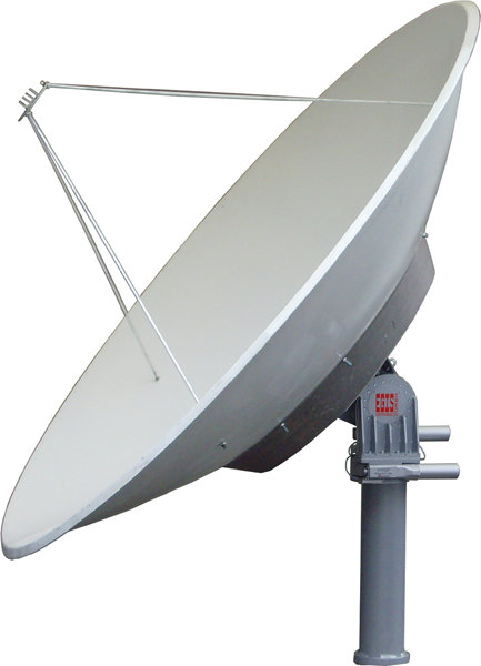
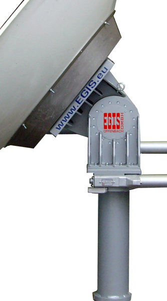
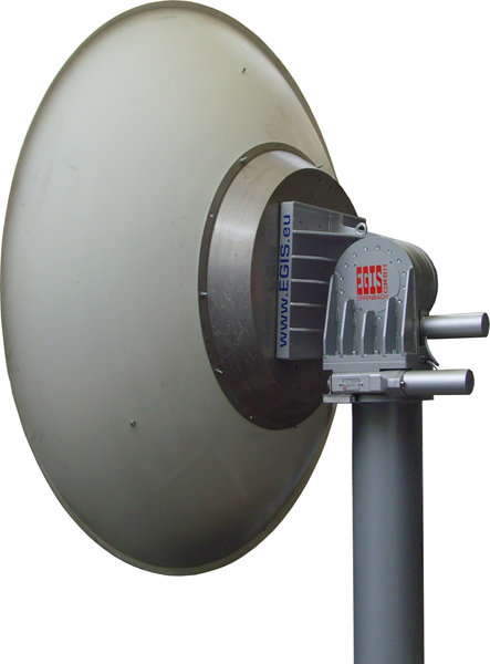
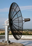
This photo shows the ProfiTracker XL
with a 3.10 m antenna(L-band) used
by EADS Astrium, one of the installers
of the Europe owned Satellite Navigation
System "GALILEO". |
|
 |
|
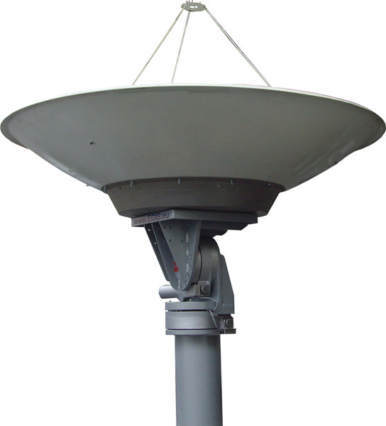
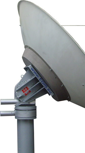
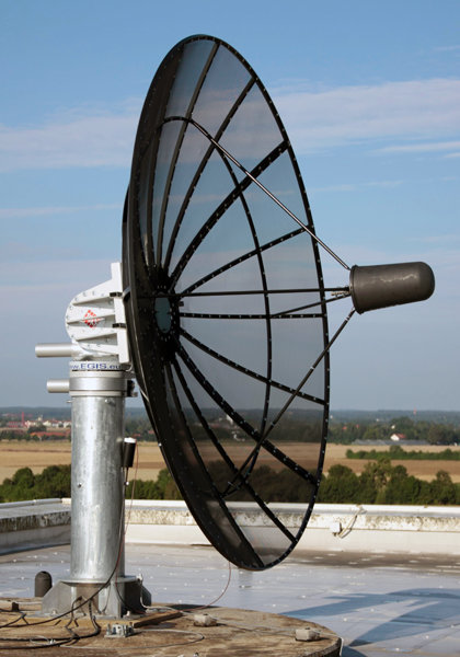
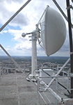
Here the XL-positioner carrying a 3.1 m
microwave antenna, on a lattice tower
in 150 m height (Belgium). |
The system can be deployed for geostationary, also inclining*** geostationary satellites, as well as for orbiting ones (LEOs). Features are:
- 90° elevation span
- 360° azimuth-rotation angle
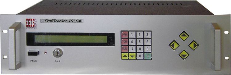
- 19�-rack-type control unit
- 400 programme places, 340 of which are already preset with current satellites
-
solid state relay
- for material-saving permanent-focussing/-tracking
- no contact-burnout, due to mechanical contactless switching
- less noise due to absence of switching or cut-off sparks
- silent control unit, because no parts are moving
- cultivated two-speed-operation, because semi-conductors can be switched on and off in high-frequency
- more accurate, because static switches enable the user to drive different speeds
- improved tracking behaviour, because the positions can be targeted more precisely by �starting� and �stopping� at reduced speed
- �True� soft start and soft-stop is achieved by using the integrated �SERVO�-function
- With time-consuming logic: in some positioning phases both of the motors are running simultaneously!
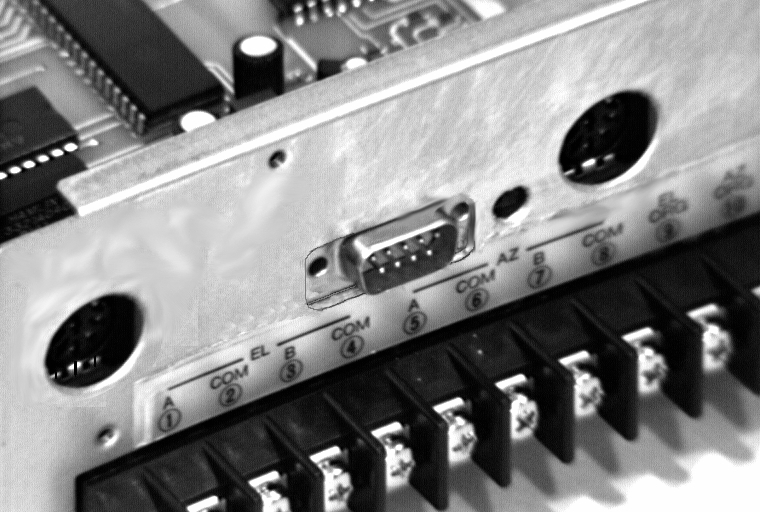
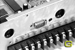
- With Receiver-interface* (image G) for connection and remote control via receiver/ sat-tuner with motor-controlled approach, adjustable transfer speed (1 to 99 pulses/sec), via 4 wires only (motor 5 to 60 V, pulse = 50 V, 100 mA max.)
- Simultaneous signal transmission, while both motors are active!
- With analogue input (AGC)
- For field-strength dependant positioning-optimisation** – the working range of the AGC-signal supports adaptation to the receiver as well in amplitude/slope as in zero-point value (max. 12 V – signal-Î� min. 0.1 V pos. & neg.)
- To optimize performance for stable sat-positions
- For geostationary, but locally inclining satellites
The searching- and tracking-behaviour (AUTO-FOCUS/- TRACKING) can be influenced in a motor-protecting way by selecting the max permissible deviation, by setting the time of the next searching cycle, by determining the searching amplitudes as well as the searching algorithm. Field strength data are taken from the AGC-output of the receiver/ Sat-tuner/ modem (but also from other linear systems), so that C-, S- and Ku-band-systems can be used. The measured analogue signals are converted into one 8-bit Word (0 – 255). The read-in clock rate/- resolution is 250 Hz! The relative field strength is permanently displayed on the control unit. A long time before one gets aware of any degradation of quality, the optimization of the field strength is performed automatically, fast and with high precision. (The AGC-connecting cable to the receiver is included in delivery.)
Of course you can search a satellite manually with such a system in a perfect way: Looking at the display, watching the AZ- and EL-angle – right/left – up/down. You may think â€�Nothing can be easierâ€�. – You are wrong! It gets even more perfect – with â€�SUPERSEARCHâ€�: During installation, you now dial up a satellite as usual. Due to mechanical mounting errors, you will – more or less – miss the satellite. Now SUPER-SEARCH flashes into action. Starting from the calculated AZ- and EL-angles, the rotor will now concentrically scan the sky by widening circles, always in line with the apex angle of your antenna. In this process you may possibly find satellites which have not been selected. Therefore this key enables the searching movements to be stopped and to be restarted. As soon as the right satellite is recognized, you may start the auto-focussing or optimize manually.
The controller respectively the system offer receiver pulse synchronization, motor sensor monitoring, motor emergency operation, focussing via RS 232-interface, park-position, direct angle selection and more (for more details, see table �Enhanced Programme-Functions�).
|
| * |
= |
Receiver-Interface: The 4 wires, normally routed from the sat-receiver to the linear actuator motor on the roof, are connected to the terminals at the rear panel of our control unit. Afterwards, the satellites can be selected arbitrarily, individually and directly using the remote-control of the sat-receiver – as with an actuator, yet much more accurately and from â€�horizon to horizonâ€�, even at the ends of the â€�Clark Beltâ€�! |
| ** |
= |
The autofocus-operation requires a very rigid mechanical connection between the antenna and the rotor. It must be possible to correlate any signal measured by the satellite receiver exactly with a specific antenna direction (thus direction of the rotor). AGC-signals shall only indicate true field-strength dependant changes, without time-shift, without image content fluctuations, and they must be free of �spike�-influences. |
| *** |
= |
To save fuel, older satellites are�inclined� in higher amplitudes: More than 50 % of all satellites are already in the �inclination-orbit�. And their number will be growing! Therefore a non-stop reception is not always possible with bigger antennas. One of the major capacities of this rotor-system is the �tracking� of such satellites: Even before the TV-spectators get aware of any degradation of the image quality, the antenna will follow the satellites� position automatically, fast and perfectly! |
|
O
|
|
COMMUNICATION INTERFACE
For communication with an external computer, the system is supplied with a serial two-way «RS 232 C data-interface» (data stream: 8 bit / no parity/ 1 stop-bit / 50 to 9900 baud with hardware-handshake). Can be used to advantage for: Alignment to and tracking of non�geostationary objects, such as stars (astronomy), space stations (ISS), amateur radio- satellites (OSCAR) and for low-flying LEO-satellites, respectively those with elliptical orbits.
Direction-defining data are transmitted to the rotor-control via a «RS 232 C data-interface». This works in the opposite direction, too: You may at any time recall information about the rotor�s operating status from the computer. The intelligent interface also allows for operation via telephone-modem. Built-in filters make it possible to operate several rotors at a single interface.
Also suitable for field-strength depending alignment to and tracking of measuring signals, e. g. meteorological probes (weather balloons), radio direction finding of locating movable transmitters. The measuring directions and the field strengths are permanently transmitted to the external computer via data-interface!
Command-Syntax-Examples:
- Rotate azimuth motor to 134.56° – "AZ = 134.56 [CR]" or
- enter elevation-position into the computer – "EL = ? [CR]"
- The instruction word �FOCUS� triggers an automatic focussing-run.
- The instruction �RESULT� arranges for an automatic read-out of operational and performance data after each auto-focussing, e. g. AZ- and EL-angle with the belonging strength of the analogue signal. The automatic read-out can transferred to a computer (as a protocol, for instance), but also directly on a printer! These data can be stored in a file on a computer�s hard drive and they are immediately available to be used with commercially available spreadsheet programmes or databases, therefore they can be displayed graphically without a special programme.
This data string additionally contains date and time. See a sample of this data string here:
Row-No.; day; date; time of day; tracking-channel; AZ-angle; EL-angle; AZ-motor-pulse; EL-motor-pulse; level of the analogue channel 1; 2; 4 formatted as follows:
00000 Mon 11.12.98 15:23:44 01 00000 00000 00000 00000 00000 00000 00000
There are more instructions available!
This interface is needed
- for PC-communication or
- for a GPS-receiver or
- for the integrated or extern web-server
Only one function can be used at the same time.
|
|
|
GPS CAPTURE FUNCTION
This function is used for automatic takeover of the global latitudes and longitudes (coordinates) from a GPS-navigator /receiver via the serial interface to the arithmetic and logic unit of the computer. In this case it is not necessary to manually enter the location of the system.
The NMEA183-protocol can be read and used.
An appropriate GPS-receiver can be found at 'COMPLETIONS'
|
|
O

|
|
POLARIZER- (SKEW) INTERFACE INTEGRATION 'POL-T1'
For the activation of a commercial polarizer (dipole- or wave-guide-polarizer) with pulse-width control. This extension can be used to save the individually adjustable polarizer position for each single satellite position. When selecting the same satellite later on, the corresponding polarizer angle will be approached automatically.
Connection: Plus, ground and pulse-width
|
|
O
|
|
WEB-SERVER INTEGRATION INTO CONTROLLER UNIT 'WEB-T1'
Integrated web-server, making EGIS-antenna-positioners controllable by means of a computer network. A choice of satellite- (A) or terrestrial- resp. waveguide positions (B) will be made available to all clients for selection and approach via Internet or Intranet. Programs, memory, logs and anything 'soft' are stored undetachably on flash memory. Any Internet browser (i. e. MS Internet Explorer, Mozilla, Apple Safari and so on) can be used platform-independant to select and approach satellites as well as positions from the net. Of course a simple hierarchy of programmable authorisations is already implemented, which will control the number of users selectively.
The use becomes transparent by a log working automatically in the background.
Caution: The control devices (Profi Tracker) requires a RS232 interface (option: pos. b1 !)
An entire satellite, a specific transponder or a defined frequency can be selected via the integrated spectrum-analyzer in order to generate the AGC-signal.
Details in pdf-format:
A. Satellite version
or
B. Terrestrial resp. microwave version
|
|
|
AZIMUTH 360° 'ENDLESS' FUNCTION
The user of the system can change the azimuth rotation range to the »360° endless»- mode. This alteration also activates a revolution counter with programmable limiting of revolutions (to avoid cable rupture). In each direction of rotation, this limitation is adjustable between 1 and 99 revolutions.
|
|
|
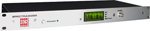
19" RACK HOUSING of the CONTROL UNIT
Control centres and technical control stations in studios, antenna head-end stations, telecommunication and satellite communication offices often require operation and control via 19�-rack-mount equipment. Therefore the control of the system has been integrated into a 19�-rack housing with 3 U x 290 mm, front-panel anodised in aluminium colour. Besides an increased HF-density, the device provides plug-in connections and an illuminated two line display, as well as a front safety lock (2 keys) to lock certain operating functions, which protects the system against unauthorized use.
LEDs are displaying driving directions and other operating states.
|
|
|
COMPLETIONS
|
|
O
|
|
1. SPECTRAMIZER 'SPEC-T1'
This device provides an AGC analogue signal for a manual and automatic field strength-related alignment of antennas.
It was designed for the �locating� as well as for the �tracking� of satellites, but also of other �mobile� HF-signals.
With the integrated spectrum-analyser, you can selectively use the whole satellite, a certain transponder or a special frequency to produce the AGC-signal.
more details in PDF format
|
|
O
|
|
2. GPS RECEIVER FOR AUTOMATIC POSITION DETECTION 'GPS-H-T1'
(Hardware- and firmware-modification)
The GPS extension for the antenna-positioner provides local position detection and subsequent angle calculation of all geostationary satellites which are visible from this position.
Receiver and GPS-antenna are integrated into a common housing and mounted to the back of the controller. If necessary, the GPS satellite signals can be transferred to the control system also externally via an included cable of 5 m in length.
The automatic read-in process of the lat/lon-data has to be actuated manually.
The power supply for the GPS extension is taken from the controlling device.
|
|
O
|
|
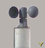
3. SHELL-ANEMOMETER/WIND-SPEED-SENSOR 'Wi-S1'
An anemometer is used to measure the locally appearing wind speeds. The 4-wire-interface on the control unit is able to read and to evaluate the signals from the anemometer.
Details:
- Three- cup system
- Ring of cups - outer diameter: 120 mm
- Diameter of the cups: 40 mm
- Installation height: 70 mm
- Material: ABS
- Pulse generator system: magnet/ reed-switch
- Pulse-rate: 60 km/h = 16.8 m/sec = 47 Hz
- Suitable to be mounted on a mast or on top of it
Please note: The 4-wire-interface can either be used to connect satellite receivers or to connect wind sensors.
|
|
O
|
|
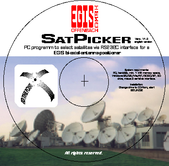
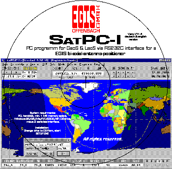
4. PC-Software for 'GEOs' 'SatPicker I'
A PC-software-programme available on CD in English language to dial up geostationary satellites via RS 232-C interface and an EGIS-antenna-positioner.
All current â€�GEOsâ€� are preinstalled within the programme. To improve clarity, satellites can be chosen – by clicking – from the complete list, be inserted in a list of preferred satellites and be saved there afterwards. Another clicking â€� and the desired satellite is defined. A bi-axial fine adjustment is also possible. These data are also non-volatile saved in the PC. The â€�Clark beltâ€� will be visualized within a desk window and the position of the current satellite will be displayed in a graphical format.
The programme is particularly suitable for journalists, correspondents and editing offices in publishing houses, broadcasting centres and translation agencies, but also for educational establishments and public authorities. Detailed operating instructions included.
Click here to see a screenshot of the programme.
System requirements: PC with hard drive with a minimum of 5 MB free storage place minimum, Windows 95/98/Me/NT/2000/XP/Vista/7, CD-drive, mouse and serial interface
|
|
O
|
|
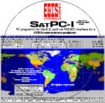
5. PC-Software for 'LEOs' 'SatPCI'
A PC-software-programme, available on CD with detailed description (in German and English language). To dial up predominantly orbiting satellites and approach/ operation of the rotor via RS 232 C-interface. The programme provides Kepler-data for about 300 satellites – â€�Geosâ€� as well as â€�Leosâ€� – and space stations (e. g. ISS). Current data can be loaded in NASA format. Lots of graphics & info like orbit data, orbit curves, calculated shadings, viewing angles and others more.
System requirements: PC with harddisk with a minimum of 5O MB free storage space, Windows 95/98/Me/NT/2000/XP/Vista/7, CD-drive, mouse and serial interface
|
|