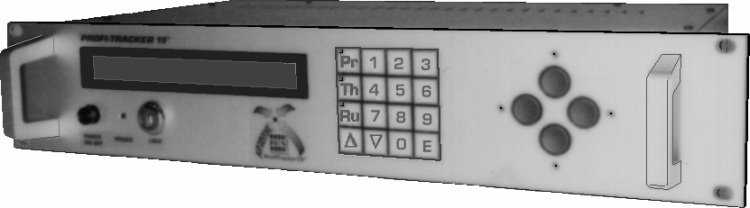
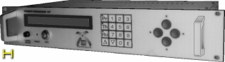
| controlpanel in 19" rack mount (2 HE) (dimensions (W x H x D): approx. 484 x 88 x 255 mm) |
|
|
 |
 |
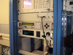
| operation at a broadcaster |
 |
Back to the homepage | 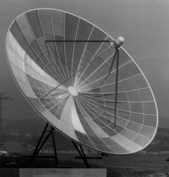 |
||
|
Bi Axial Positioning Control
for ACTUATORS & GEAR MOTORS |
||||
| CONTENT: system description | extensions and upgrades | technical specifications | price list |
|
For automatic selection of satellites and tracking of inclining satellites. Ready for yagi and radar antennas. Intelligent self-learning control system.
|
|
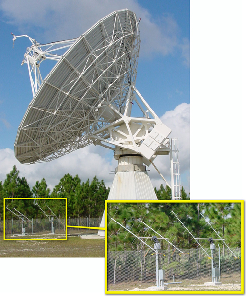 |
Professionals – one of a breed!
EGIS rotors with Yagi antennas for ATS-3 satellite (also used for commmanding & telemetry VHF on GOES-3) 149 MHz & 137 MHz and LES-9 satellite 302 MHz & 249 MHz. All of the above antennas are used in support of the "United States Antarctic Program". The 'Malabar Satellite Operations Center' of the University of Miami provides communications to various research stations on the Antarctic continent, including the 'Geographic South Pole station', and 'Palmer station' in the Antarctic. |
| SYSTEM DESCRIPTION | back to the beginning | |
|
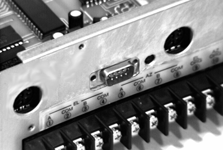
The AutoTracker III is a microprocessor based control unit including the positioning logic as well as the power output unit for the rotor motors. It allows to drive two separate motors (max. 2.5 Amps each) directly with Reed-Pulse Sensors for the elevation and the azimuth.
The read-only memory contains information about all stationary satellites around the world. On the fly, you may – within the physical limits of the external devices – select any desired satellite. Only mechanical unlinearities of the system have to be corrected manually. If necessary, the system now will automatically track the inclining orbit. In order to allow this automatic tracking, the AGC voltage from the satellite receiver has to be fed to the analogue input of the control unit, which will then optimize the positioning for maximum field strength. The operational range of the AGC signal can be matched to the satellite receiver in terms of amplitude/sensitivity as well as of null (max. 12 V, min. 0.1 V – each polarity). The search and tracking quality (AUTO FOCUS/AUTO TRACKING) may be influenced by selection of maximum deviation, next search cycle, fixing of search amplitudes and search algorithm. The field strength information is delivered, by means of the AGC voltage, by the satellite tuner thus allowing the reception of signals within the C, S and Ku bands. The display of the control unit continuously shows the relative signal strength. Before dropouts can hamper the transmission of data or even lead to a visual loss of quality, the system will automatically optimize the field strength, fast and with ultimate precision. The necessary AGC connecting cable is included in your package. For connecting and the remote control via sat-tuner the control computer features a receiver interface with settable transfer rate (1 to 99 pulses/sec.) using 4 wires only (motor: 5 to 60 V, pulse: max. 50 V/100 mA); simultaneously transferring signals during active motors too!
These functions and a lot more are efficiently supported by many system helps:
|
 |
 |
|
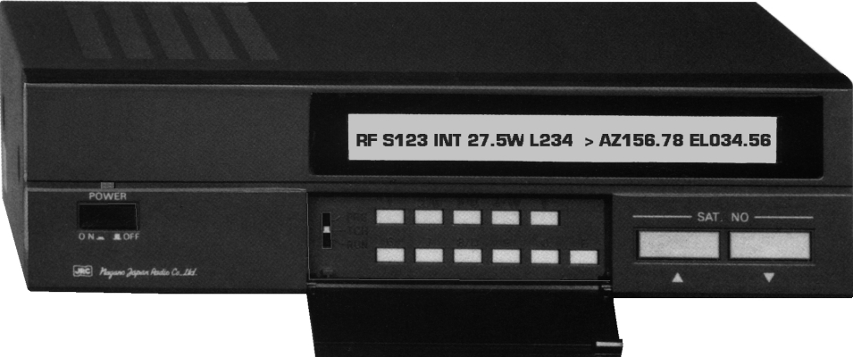
| computer with display (desktop version) | 19" rack version |
| EXTENSIONS & OPTIONS | back to the beginning | |
| SPECIFICATIONS | back to the beginning | |
| BASIS VERSION | |||||
| power supply | 230/115 V AC or 10 up to 28 V DC (option) | ||||
| motor control | 24 V DC/max. 2.5 Amp. | ||||
| pulse frequency | max. 200 Hz | ||||
| pulse width | min. 2.5 msec. | ||||
| resolution | 65,000 pulse/axis | ||||
| RELAIS- & POWER-EXTENDER | |||||
| power supply | AC 230/150 V AC or DC 6 up to 48 V | ||||
| motor control | AC max. 6 Amp. – DC max. 12 Amp. | ||||
| PRICE LIST | back to the beginning | |
| VERSION | | (excl. VAT) EURO | |||||||||
| AutoTracker III | bi-axial positioner for external gear motors (basis version) | 1 998.00 | ||||||||
| OPTIONS | | (excl. VAT) EURO | |||||||||
| Data-Interface | hard- & software extension RS 232 C interface | 798.00 | ||||||||
| Relais- & Power-Extender | power, control & switch extender (DC- or AC-version) | 398.55 | ||||||||
| MotionControl | hard- & software extension for basis version & extender | 989.00 | ||||||||
| GR-19 | basis unit (& if given power extender) fitted into a 19" rack mount (2 UH) | 998.00 | ||||||||
| SPECTRAMIZER | spectrum analyzer incl. AGC outlet in 19" rack | 1 997.50 | ||||||||
| EGPOSER II | web server for Antenna-Rotor | 3 122.50 | ||||||||
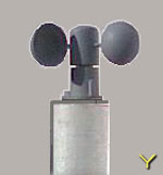
| Wi-S1 | wind-speed-sensor/shell-anemometer | 317.35 | ||||||||
| We also offer power supplies according to your motor specifications. | ||
| Subject to technical change without prior notice. |
| CONTENT: system description | extensions and upgrades | technical specifications | price list |
| EGIS Cloud |

|
E G I S
EQUIPMENT GESELLSCHAFT für INTERN. ELEKTRONIK SYSTEME GmbH |
Flutstraße 34 – 36
D–63071 OFFENBACH/MAIN Tel.: 069 / 85 83 27 Fax: 069 / 85 78 63 |
| << Homepage | 20 minutes from Airport Frankfurt – 20 minutes to Frankfurt City | E-Mail: Sat@egis.eu |